ich habe folgendes Problem:
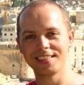
Ich versuche einzelne Kontursegmente zu einem Kreis zusammenzufügen. Die Anzahl der Segmente ist im Parameter N hinterlegt. Bei kleinen N funktioniert alles wie es soll, jedoch habe ich bei größeren N (hier 36) einen Versatz in der Zeichnung. Woher kommt das und wie kann ich es beheben?
Hier das Beispiel:
\documentclass{standalone}
\usepackage{tikz}
\usetikzlibrary{fpu, calc, angles, intersections}
\usepackage{pgfplots}
\pgfplotsset{compat=1.18}
\usepackage{comment}

\newcommand{\radiusOHL}[3]{
\path
(#1)coordinate(M)% Mittelpunkt
(#2)coordinate(A)% Anfangskoordinate
(#3)coordinate(B)% Endkoordinate
;
\path
let
\p1=(M), \p2=(A),
\n1={veclen({\x2-\x1},{\y2-\y1})}
in
pic[draw=black,angle radius=\n1]{angle=A--M--B} ;
}


\begin{document}
\begin{tikzpicture}
% Parameter
\def\N{36}
\def\rot{90-360/\N}
\def\bzhs{0.3}
\def\nutoeffnung{0.8}
\def\do{10}
\def\di{7}
\def\hzhs{0.4}
\def\hrues{0.4}
\def\hzks{0.1}

\def\p{2}
\def\delta{0.2}
\def\alphap{0.5}
\def\dw{1}

\def\rotorcolor{gray!50}
\def\statorcolor{gray}

% Berechnungen
\def\taupdeg{360/(2*\p)}
\def\tauNdeg{360/\N}
\pgfmathsetmacro\dzk{\di+\hzks*(\do-\di)};
\pgfmathsetmacro\drue{\do-\hrues*(\do-\di)};
\pgfmathsetmacro\dzhu{\do-(\hrues+\hzhs)*(\do-\di)};
\pgfmathsetmacro\dro{\di-2*\delta};


% Hilfslinien
\path[color=gray,dashed, name path=DAS] (0,0)++(\rot:\do/2) arc(\rot:\rot+2*360/\N:\do/2);% node {\tiny DAS};
\path[color=gray,dashed, name path=DIS] (0,0)++(\rot:\di/2) arc(\rot:\rot+2*360/\N:\di/2);% node {\tiny DIS};
\path[color=gray,dashed, name path=DRUE] (0,0)++(\rot:\drue/2) arc(\rot:\rot+2*360/\N:\drue/2);% node {\tiny DRUE};
\path[color=gray,dashed, name path=DZK] (0,0)++(\rot:\dzk/2) arc(\rot:\rot+2*360/\N:\dzk/2);% node {\tiny DZK};
\path[color=gray,dashed,name path=GL] (0,0) -- (0, 1.1*\do/2);% node[above] {\tiny GL};
\path[color=gray,dashed,name path=GZ] (0,0) -- ({1.1*\do/2*sin(\nutoeffnung*360/(2*\N))}, {1.1*\do/2*cos(\nutoeffnung*360/(2*\N))});% node[above] {\tiny GZ};
\path[color=gray,dashed,name path=GR] (0,0) -- ({1.1*\do/2*sin(360/(2*\N))}, {1.1*\do/2*cos(360/(2*\N))});% node[above] {\tiny GR};

% Schnittpunkte & Koordinaten
\path[name intersections={of=GL and DIS}](intersection-1) coordinate (c1);% node {\tiny 1};
\path[name intersections={of=GZ and DIS}](intersection-1) coordinate (c2);% node {\tiny 2};
\path[name intersections={of=GZ and DZK}](intersection-1) coordinate (c3);% node {\tiny 3};
\path (c3);
\pgfgetlastxy{\xa}{\ya};
\pgfmathsetmacro\bzh{2*\bzhs*\xa};
\path[name path=BZH] ({\bzh/2 pt},0) -- ({\bzh/2 pt},1.1*\drue/2);
\path ({\bzh/2 pt},\dzhu/2) coordinate (c4);% node{\tiny 4};% node{\tiny 5};
\path[name intersections={of=BZH and DRUE}](intersection-1) coordinate (c5);% node {\tiny 5};
\path[name intersections={of=GR and DRUE}](intersection-1) coordinate (c6);% node {\tiny 6};
\path[name intersections={of=GR and DAS}] (intersection-1) coordinate (c7);% node {\tiny 7};
\path[name intersections={of=GL and DAS}](intersection-1) coordinate (c8);% node {\tiny 8};
\path[name path=HLW] (c3) -- (c4);


% Spiegelung
\foreach \x in {2,3,4,5,6,7,8} {
\path (c\x);
\pgfgetlastxy{\xc}{\yc};
\path (-\xc, \yc) coordinate (c\x m);% node{\tiny \x m};
}


% Koordinatendrehung STATOR

%xr1s = x*cos phi+y*sin phi
%yr1s = -x*sin phi + y*cos phi

\pgfmathsetmacro\k{\N-1}
%\foreach \i in {0,1,2,...,\k} {
\foreach \i in {0,1,2,3,4,5} {

\pgfmathsetmacro\phirot{\i*\tauNdeg}

\foreach \x in {2,3,4,5,6,7,8} {
\path (c\x);
\pgfgetlastxy{\xc}{\yc};
\path ({\xc * cos(\phirot)+\yc * sin(\phirot)}, {-\xc * sin(\phirot)+\yc * cos(\phirot)}) coordinate (c\x rot);% node[above]{\scalebox{.2}{r\x rot}};

\path (c\x m);
\pgfgetlastxy{\xc}{\yc};
\path ({\xc * cos(\phirot)+\yc * sin(\phirot)}, {-\xc * sin(\phirot)+\yc * cos(\phirot)}) coordinate (c\x mrot);% node[above]{\scalebox{.2}{r\x mrot}};
}

% Kontur
\radiusOHL{{0,0}}{c7rot}{c7mrot};
\radiusOHL{{0,0}}{c6rot}{c5rot};
\draw (c5rot) -- (c4rot);
\draw (c4rot) -- (c3rot);
\draw (c3rot) -- (c2rot);
\radiusOHL{{0,0}}{c2rot}{c2mrot};
\draw (c2mrot) -- (c3mrot);
\draw (c3mrot) -- (c4mrot);
\draw (c4mrot) -- (c5mrot);
\radiusOHL{{0,0}}{c5mrot}{c6mrot};

};
\end{tikzpicture}
\end{document}