Legendeneintrag in falscher Farbe nach \tikzexternalize Thema ist als GELÖST markiert

Tabellen und Grafiken erstellen und anordnen


orikson

Legendeneintrag in falscher Farbe nach \tikzexternalize

Beitrag von orikson »

Hallo,

ich brauche für meine Bachelorarbeit ein Diagramm mit zwei getrennten Y-Achsen. Allerdings will ich beide Kurven in einer Legende stehen haben. Das ganze funktioniert bereits super, solange ich die Grafiken nicht extern erzeugen lasse (mit \tikzexternalize). Das muss ich aber, da mir sonst Latex immer wegen Speicherproblemen meckert und lange dauert.

So habe ich immer das Problem, dass mein erster Legendeneintrag hinter einer schwarzen Linie steht, obwohl die eigentlich blau sein sollte.

Gibt's dafür eine schöne Lösung oder vielleicht sogar einen ganz anderen Ansatz für Graphen mit 2 Achsen?

Besten Dank :roll:
\documentclass[12pt, a4paper]{scrreprt}

% einbinden der pgfplot-Graphen
\usepackage{tikz}

% pgfplots kann Graphen zeichnen
\usepackage{pgfplots}

% Erstellung von Grafiken, Diagrammen etc auslagern um Compiliergeschwindigkeit zu erhöhen und Speicherbedarf zu reduzieren
\usepgfplotslibrary{external}
\tikzexternalize

% Beginn des eigentlichen Dokuments
\begin{document}

\begin{figure}[h]
\begin{tikzpicture}

\begin{axis}[
	axis y line* = left,
	axis x line = none,
	]
	\addplot [color = blue, smooth] coordinates {(1,0) (5,4)};
	\label{data:Line1}
\end{axis}

\begin{axis}[
	axis y line* = right,
	ymin = 0,
	ymax = 6
	]
	\addlegendimage{/pgfplots/refstyle=data:Line1}
	\addlegendentry{Blau}
	
	\addplot [color = cyan, smooth] coordinates {(0,1) (5,4)};
	\addlegendentry{Cyan} 

\end{axis}

\end{tikzpicture}
\end{figure}

\end{document}


orikson

Beitrag von orikson »

Danke für den Hinweis, das Problem scheint es ja noch nicht lange zu geben, oder?

Ich konnte das Problem nur dadurch umgehen in dem ich vor das jeweilige Bild, genauer gesagt direkt vor das jeweilige \begin{tikzpicture}, ein \tikzset{external/export next=false} eingefügt habe.

Marcel
Forum-Anfänger
Forum-Anfänger
Beiträge: 33
Registriert: Mo 8. Jun 2015, 20:07

Ähnliches Problem

Beitrag von Marcel »

Hallo,

ich habe ein ganz ähnliches Problem. Ich brauche auch ein Diagramm mit zwei y-Achsen und habe seit dem erstellen eine falsche Farbe in der Legende.
\documentclass[a4paper,12pt,headsepline]{scrartcl}
\usepackage[ngerman]{babel}
\usepackage{tikz}
\usepackage{pgfplots}
\pgfplotsset{width=7cm,compat=1.12}
\usepackage{float}
\usepackage{acronym}
\usepackage{siunitx}

\begin{document}

\begin{figure}[H] 
\begin{tikzpicture}
\begin{axis}[
		title=Messung,
		width=13cm,
		height=7cm,
		ymin=15,
		ymax=20,
		axis y line=right,
		axis x line=bottom,
		enlargelimits=0.1,
		ylabel={Strömungsgeschwindigkeit \Big[$\SI{}{\metre\per\second}											$\Big]},
		symbolic x coords={Poly 1,Poly 2,Poly 3,
		Poly 4, Auto 1, Auto 2, Auto 3, Auto 4, Trimmer 1, Trimmer 2, Tetra 1, Tetra 2},
		xtick=data,
		nodes near coords,		
		every node near coord/.append style={
                font=\scriptsize,
                /pgf/number format/.cd,
                fixed zerofill,
                precision=1},
		x tick label style={rotate=45,anchor=east}
		]
\addplot [color=blue,
		line legend,
		sharp plot,
		]
coordinates{(Poly 1, 16.24)
		(Tetra 2, 16.40 )}; 
\end{axis}

\begin{axis}[
		width=13cm,
		height=7cm,
		ymin=0.980e+05,
		ymax=1.030e+05,
		axis y line=left,
		axis x line=none,
		scaled y ticks=manual:
						{$\cdot10^{-5}$}{%
						\pgfmathparse{#1/100000}%
						},
		yticklabel style={
						/pgf/number format/fixed zerofill,
						/pgf/number format/precision=3},
		enlargelimits=0.1,
		ylabel={Druck \Big[$\SI{}{\pascal}$\big]},
		legend pos=north east,
        legend cell align=left,		
		legend style={at={(0.7,-0.35)}},
		label style=sloped,
		symbolic x coords={Poly 1,Poly 2,Poly 3,
		Poly 4, Auto 1, Auto 2, Auto 3, Auto 4, Trimmer 1, Trimmer 2, Tetra 1, Tetra 2},
		xtick=data,
		nodes near coords,
		every node near coord/.append style={
                font=\scriptsize,
                /pgf/number format/.cd,
                fixed zerofill,
                precision=3},
		point meta=y*10^-5,
		x tick label style={rotate=45,anchor=east},
		]
\addplot [color=red,
		line legend,
		sharp plot,
		]
coordinates{(Poly 1, 1.0098e+05)
		(Tetra 2, 1.0164e+05)}; 
			
	\addlegendimage{/pgfplots/refstyle}
	\addlegendentry{Druck}
    \addlegendentry{Strömungsgeschwindigkeit} 
\end{axis}
\end{tikzpicture}
\end{figure}
\end{document}

esdd
Forum-Meister
Forum-Meister
Beiträge: 2561
Registriert: So 7. Feb 2010, 16:36

Beitrag von esdd »

Dein Problem hat meiner Meinung nach nichts mit dem anderen zu tun. Mach doch bitte das nächste Mal einfach ein neues Thema auf.

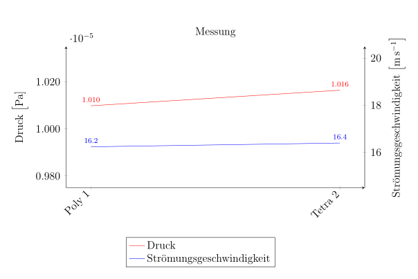
Du musst nach dem ersten \addplot...; noch ein Label wie \label{pgfplots:plot1} setzen. Dann kannst Du das in \addlegendimage als Referenz verwenden:
\documentclass[a4paper,12pt,headsepline]{scrartcl} 
\usepackage[utf8]{inputenc}
\usepackage[ngerman]{babel} 
\usepackage{pgfplots} 
\pgfplotsset{width=7cm,compat=1.12} 
\usepackage{siunitx} 

\begin{document} 
\begin{tikzpicture} 
\begin{axis}[ 
title=Messung, 
width=13cm, 
height=7cm, 
ymin=15, 
ymax=20, 
axis y line=right, 
axis x line=bottom, 
enlargelimits=0.1, 
ylabel={Strömungsgeschwindigkeit \Big[$\SI{}{\metre\per\second} $\Big]}, 
symbolic x coords={Poly 1,Poly 2,Poly 3, 
Poly 4, Auto 1, Auto 2, Auto 3, Auto 4, Trimmer 1, Trimmer 2, Tetra 1, Tetra 2}, 
xtick=data, 
nodes near coords, 
every node near coord/.append style={ 
font=\scriptsize, 
/pgf/number format/.cd, 
fixed zerofill, 
precision=1}, 
x tick label style={rotate=45,anchor=east} 
] 
\addplot [color=blue, 
line legend, 
sharp plot, 
] 
coordinates{(Poly 1, 16.24) 
(Tetra 2, 16.40 )};
\label{pgfplots:plot1}% <- hier muss ein Label gesetzt werden
\end{axis} 

\begin{axis}[ 
width=13cm, 
height=7cm, 
ymin=0.980e+05, 
ymax=1.030e+05, 
axis y line=left, 
axis x line=none, 
scaled y ticks=manual: 
{$\cdot10^{-5}$}{% 
\pgfmathparse{#1/100000}% 
}, 
yticklabel style={ 
/pgf/number format/fixed zerofill, 
/pgf/number format/precision=3}, 
enlargelimits=0.1, 
ylabel={Druck \Big[$\SI{}{\pascal}$\big]}, 
legend pos=north east, 
legend cell align=left, 
legend style={at={(0.7,-0.35)}}, 
label style=sloped, 
symbolic x coords={Poly 1,Poly 2,Poly 3, 
Poly 4, Auto 1, Auto 2, Auto 3, Auto 4, Trimmer 1, Trimmer 2, Tetra 1, Tetra 2}, 
xtick=data, 
nodes near coords, 
every node near coord/.append style={ 
font=\scriptsize, 
/pgf/number format/.cd, 
fixed zerofill, 
precision=3}, 
point meta=y*10^-5, 
x tick label style={rotate=45,anchor=east}, 
] 
\addplot [color=red, 
line legend, 
sharp plot, 
] 
coordinates{(Poly 1, 1.0098e+05) 
(Tetra 2, 1.0164e+05)}; 

\addlegendimage{/pgfplots/refstyle={pgfplots:plot1}}% <- und hier muss das Label benutzt werden
\addlegendentry{Druck} 
\addlegendentry{Strömungsgeschwindigkeit} 
\end{axis} 
\end{tikzpicture} 
\end{document}
Gruß
Elke

Bild
Dateianhänge
gl_addlegendimage.png
gl_addlegendimage.png (20.84 KiB) 2740 mal betrachtet

Marcel
Forum-Anfänger
Forum-Anfänger
Beiträge: 33
Registriert: Mo 8. Jun 2015, 20:07

Beitrag von Marcel »

Hey vielen Dank. Hat super funktioniert. Sorry fürs nächste mal weiß ich es.

Antworten