von lenherrg » Di 6. Feb 2018, 15:03
Liebe Experten,
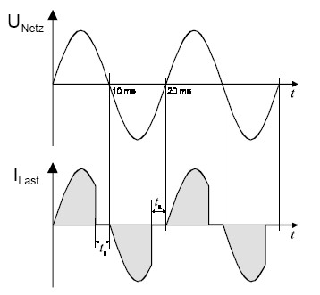
der Plot zeigt eine Phasenabschnitssteurung, z.B. in einem Dimmer.
Gerne möchte ich die Fläche unterhalb der Funktion (bei der zweiten Halbwelle oberhalb) bis zur x-Achse einfärben.
Ich habe verschiedenes probiert, bin aber leider gescheitert.
Ich wäre froh um Hilfe. Danke im voraus!!
% Das ist mein LaTeX-Dokument.
\documentclass[12pt,a4paper]{article}
\usepackage[left=2cm,right=2cm,top=2cm,bottom=2cm]{geometry}
\usepackage{tikz} 		% Kopf- und Fusszeile, Grid (auch Farbe und Grafik)


\begin{document}
Phasenabschnittsteuerung\\
\begin{center}
\begin{tikzpicture}[
x=0.3cm, y=1cm,  scale=1.0,
font=\footnotesize,
>=latex   %Voreinstellung für Pfeilspitzen
]

% Gitternetzlinien
%\draw[xstep=1.2cm, ystep=0.8cm, line width=0.1mm, color=lightgray] (0,-2.25) grid (42.25,2.25);

% x-Achse
\draw[->] (-0,0) -- (35,0) node[below] {$t$};
%Zahlen auf x-Achse
\foreach \x in {10,20,...,30}
\draw[shift={(\x,0)},color=black] (0pt,2pt) -- (0pt,-2pt) node[below] {};

% y-Achse
\draw[->] (0,-2.5) -- (0,2.5) node[left] {$U$};

\draw[thick,color=gray, line width = 0.5pt, dotted] plot[samples=500, domain=0:3.18*pi]
(\x,{2*sin((0.1*pi)*\x r)});
\draw[thick,color=gray, line width = 0.5pt, dotted] plot[samples=500, domain=3.18*pi:6.37*pi]
(\x,{2*sin((0.1*pi)*\x r)});
\draw[thick,color=gray, line width = 0.5pt, dotted] plot[samples=500, domain=6.37*pi:9.55*pi]
(\x,{2*sin((0.1*pi)*\x r)});
\draw[thick,color=gray, line width = 0.5pt, dotted] plot[samples=500, domain=9.55*pi:10.5*pi]
(\x,{2*sin((0.1*pi)*\x r)});
\node[] at (25, -1.75) {\footnotesize \textcolor{black}{50\,\% Helligkeit}};
\draw[line width = 1pt, blue] (10,0) -- (5,0);
\draw[line width = 1pt, blue] (5,0) -- (5,2);
\draw[thick,color=gray, line width = 1pt, blue] plot[samples=500, domain=0*pi:1.57*pi]
(\x,{2*sin((0.1*pi)*\x r)});
\draw[line width = 1pt, blue] (20,0) -- (15,0);
\draw[line width = 1pt, blue] (15,0) -- (15,-2);
\draw[thick,color=gray, line width = 1pt, blue] plot[samples=500, domain=3.18*pi:4.75*pi]
(\x,{2*sin((0.1*pi)*\x r)});
\draw[line width = 1pt, blue] (30,0) -- (25,0);
\draw[line width = 1pt, blue] (25,0) -- (25,2);
\draw[thick,color=gray, line width = 1pt, blue] plot[samples=500, domain=6.36*pi:7.93*pi]
(\x,{2*sin((0.1*pi)*\x r)});
\end{tikzpicture}
\end{center}


\end{document}
% Ende des Dokumentes
Das beigefügte Bild zeigt, wie ich es gerne hätte.[/code]
Vielen herzlichen Dank im voraus!
LenherrG
- Dateianhänge
-

- Phasenabschnitt.jpg (14.57 KiB) 3389 mal betrachtet
Liebe Experten,
der Plot zeigt eine Phasenabschnitssteurung, z.B. in einem Dimmer.
Gerne möchte ich die Fläche unterhalb der Funktion (bei der zweiten Halbwelle oberhalb) bis zur x-Achse einfärben.
Ich habe verschiedenes probiert, bin aber leider gescheitert.
Ich wäre froh um Hilfe. Danke im voraus!!
[code]% Das ist mein LaTeX-Dokument.
\documentclass[12pt,a4paper]{article}
\usepackage[left=2cm,right=2cm,top=2cm,bottom=2cm]{geometry}
\usepackage{tikz} % Kopf- und Fusszeile, Grid (auch Farbe und Grafik)
\begin{document}
Phasenabschnittsteuerung\\
\begin{center}
\begin{tikzpicture}[
x=0.3cm, y=1cm, scale=1.0,
font=\footnotesize,
>=latex %Voreinstellung für Pfeilspitzen
]
% Gitternetzlinien
%\draw[xstep=1.2cm, ystep=0.8cm, line width=0.1mm, color=lightgray] (0,-2.25) grid (42.25,2.25);
% x-Achse
\draw[->] (-0,0) -- (35,0) node[below] {$t$};
%Zahlen auf x-Achse
\foreach \x in {10,20,...,30}
\draw[shift={(\x,0)},color=black] (0pt,2pt) -- (0pt,-2pt) node[below] {};
% y-Achse
\draw[->] (0,-2.5) -- (0,2.5) node[left] {$U$};
\draw[thick,color=gray, line width = 0.5pt, dotted] plot[samples=500, domain=0:3.18*pi]
(\x,{2*sin((0.1*pi)*\x r)});
\draw[thick,color=gray, line width = 0.5pt, dotted] plot[samples=500, domain=3.18*pi:6.37*pi]
(\x,{2*sin((0.1*pi)*\x r)});
\draw[thick,color=gray, line width = 0.5pt, dotted] plot[samples=500, domain=6.37*pi:9.55*pi]
(\x,{2*sin((0.1*pi)*\x r)});
\draw[thick,color=gray, line width = 0.5pt, dotted] plot[samples=500, domain=9.55*pi:10.5*pi]
(\x,{2*sin((0.1*pi)*\x r)});
\node[] at (25, -1.75) {\footnotesize \textcolor{black}{50\,\% Helligkeit}};
\draw[line width = 1pt, blue] (10,0) -- (5,0);
\draw[line width = 1pt, blue] (5,0) -- (5,2);
\draw[thick,color=gray, line width = 1pt, blue] plot[samples=500, domain=0*pi:1.57*pi]
(\x,{2*sin((0.1*pi)*\x r)});
\draw[line width = 1pt, blue] (20,0) -- (15,0);
\draw[line width = 1pt, blue] (15,0) -- (15,-2);
\draw[thick,color=gray, line width = 1pt, blue] plot[samples=500, domain=3.18*pi:4.75*pi]
(\x,{2*sin((0.1*pi)*\x r)});
\draw[line width = 1pt, blue] (30,0) -- (25,0);
\draw[line width = 1pt, blue] (25,0) -- (25,2);
\draw[thick,color=gray, line width = 1pt, blue] plot[samples=500, domain=6.36*pi:7.93*pi]
(\x,{2*sin((0.1*pi)*\x r)});
\end{tikzpicture}
\end{center}
\end{document}
% Ende des Dokumentes [/code]
Das beigefügte Bild zeigt, wie ich es gerne hätte.[/code]
Vielen herzlichen Dank im voraus!
LenherrG