von esdd » Do 10. Dez 2020, 16:15
Vermutlich ist es keine gute Idee, Teile der Abbildung als pic zu speichern. Schon das erste mit dem \graph macht Probleme. Gibt man diesem pic bei Verwendung einen Namen wird der Pfeil über den Startnode gezeichnet. Ich kann jetzt allerdings leider nicht erklären, warum das passiert.
\documentclass{standalone}
\usepackage{tikz}
\usetikzlibrary{graphs}
\tikzset{
    dataStructure/.pic={\graph[nodes={draw, circle}] {A[name=A] -> B[name=B];};}
}
\begin{document}
\begin{tikzpicture}
    \pic[pic type=dataStructure];
    \path (0,-1) pic[name=test,pic type=dataStructure];
\end{tikzpicture}
\end{document}
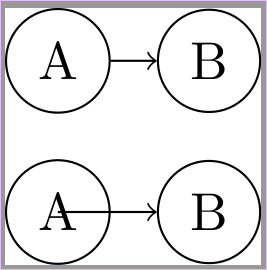
- gl_pic1.png (16.13 KiB) 1854 mal betrachtet
Dein Problem mit der Ausrichtung kommt daher, dass ein pic kein Node ist. Es hat keinen west etc. Anker, sondern wird immer mit seinem Ursprung an der aktuellen Position eingefügt.
Mit
\pic[name=dataStructure, pic type=dataStructure, anchor=west];
wird das pic vom Typ dataStructure mit seinem Ursprung im Ursprung des tikzpicture eingefügt. Die Option anchor=west wird an die Nodes des pic weitergegeben. Deshalb wird beispielsweise der Node A mit seinem west Anker im Ursprung des pic eingefügt.
Mit
\pic[name=process, pic type=process, below=of dataStructure-border, anchor=west];
wird der Ursprung des pic vom Typ process unterhalb des Node dataStructure-border bzw. dessen south Anker eingefügt. Die Option anchor=west wird wieder an die Nodes des pic weitergegeben. Deshalb wird auch hier der Node A mit seinem west Anker im Ursprung des pic eingefügt.
Damit das besser sichtbar wird, habe ich in Deine Zeichnung ein paar zusätzliche Punkte eingefügt:
 1854 mal betrachtet")
\documentclass{standalone}
\usepackage{tikz}
\usetikzlibrary{arrows.meta,positioning,graphs,fit}
\begin{document}
\begin{tikzpicture}
    \tikzset{
        border/.style = {line width=.6mm, gray, solid},
        flow/.style = {line width=0.6mm, cyan, dashed},
        sublineText/.style = {text width=2.5cm, align=center},
        arrow/.style = {-Stealth, flow},
        headerText/.style = {font=\large, align=center, rotate=90},
        markpoint/.style={circle,fill=#1,inner sep=1pt,anchor=center},% zum Markieren von Punkten
        picorigin/.style={markpoint=red},% zum Sichtbarmachen des pic-Ursprungs
        % Define the data structure block:
        dataStructure/.pic = {
            \node[picorigin,name=-picorigin]{};% Ursprung des pic markieren
            \graph[nodes={draw, circle}] {
                A[name=A] -> B[name=B];
            };
            % Draw the border:
            \node[name=-border, rectangle, draw, border, fit = (A) (B)] {};
        },
        % Define the process block:
        process/.pic = {
            \node[picorigin,name=-picorigin]{};% Ursprung des pic markieren
            \begin{scope}[node distance=32mm]
                \node[name=start] {A};
                \node[name=startText, sublineText, below=-2mm of start] {{\tiny{subline}}};
                \node[name=b, right=of start] {B};
                \node[name=bText, sublineText, below=-2mm of b] {{\tiny{subline}}};
                \node[name=c, right=of b] {C};
                \node[name=cText, sublineText, below=-2mm of c] {{\tiny{subline}}};
                \node[name=d, right=of c] {D};
                \node[name=dText, sublineText, below=-2mm of d] {{\tiny{subline}}};
                \node[name=e, below=10mm of d] {E};
                \node[name=eText, sublineText, below=-2mm of e] {{\tiny{subline}}};
                \node[name=f, below=10mm of b] {F};
                \node[name=fText, sublineText, below=-2mm of f] {{\tiny{subline}}};
                \node[name=restart, right=14mm of start] [fill=cyan,circle] {};
            \end{scope}
            % Draw the path (flow):
            \draw[arrow] (start) -- (b);
            \draw[arrow] (f.west) to[bend left=40] (restart.south);
            \draw[flow] (b) -- (c) -- (d) (d.east)
                        to[bend left=90] (e.east) (e) -- (f);
            % Draw the border:
            \node[name=-border, rectangle, draw, border, fit = (start) (startText) (eText)] {};
        }}
    % Ursprung des tikzpictures markieren:
    \node[markpoint=green,inner sep=2pt]{};
    % Draw the data structure block:
    \pic[name=dataStructure, pic type=dataStructure, anchor=west];
    \node[name=dataStructureHeader, headerText, left=of dataStructure-border.west, anchor=south] {Data};
    % Draw the process block:
    \pic[name=process, pic type=process, below=of dataStructure-border, anchor=west];
    \node[name=processHeader, headerText, left=of process-border.west, anchor=south] {Process};
    % Ausrichtung sichtbar machen
    \draw[green] (dataStructure-border)--(process-picorigin)node[pos=0,markpoint=blue]{};
\end{tikzpicture}
\end{document}
Nun kann man zwar im konkreten Beispiel dafür sorgen, dass der Ursprung des zweiten pic irgendwo auf dessen linken Rand liegt und damit die Ausrichtung erreichen, wenn man das zweite pic unterhalb des south west Ankers des dataStructure-border Nodes einfügt. Auch die Breite des Rahmens des ersten pic lässt sich passend zeichnen, aber das löst mindestens nicht das Problem mit \graph:
\documentclass{standalone}
\usepackage[T1]{fontenc}
\usepackage{tikz}
\usetikzlibrary{arrows.meta,positioning,graphs,fit}

\begin{document}
\begin{tikzpicture}
    \tikzset{
        border/.style = {line width=.6mm, gray, solid},
        flow/.style = {line width=0.6mm, cyan, dashed},
        sublineText/.style = {text width=2.5cm, align=center},
        arrow/.style = {-Stealth, flow},
        headerText/.style = {font=\large, align=center, rotate=90},
        picorigin/.style={circle,fill=red,inner sep=1pt,anchor=center},% zum Sichtbarmachen des pic-Ursprungs
        % Define the data structure block:
        dataStructure/.pic = {
            \node[picorigin,name=-picorigin]{};% Ursprung des pic markieren
            \graph[nodes={draw, circle}] {
                A[name=A] -> B[name=B];
            };
            % border:
            \node[name=-border, rectangle, fit = (A) (B)] {};% ohne zu zeichnen
        },
        % Define the process block:
        process/.pic = {
            \node[picorigin,name=-picorigin]{};% Ursprung des pic markieren
            \begin{scope}[node distance=32mm]
                \node[name=startText, sublineText] at(\pgfkeysvalueof{/pgf/inner xsep},0) {{\tiny{subline}}};
                \node[name=start, above=-2mm of startText] {A};
                \node[name=b, right=of start] {B};
                \node[name=bText, sublineText, below=-2mm of b] {{\tiny{subline}}};
                \node[name=c, right=of b] {C};
                \node[name=cText, sublineText, below=-2mm of c] {{\tiny{subline}}};
                \node[name=d, right=of c] {D};
                \node[name=dText, sublineText, below=-2mm of d] {{\tiny{subline}}};
                \node[name=e, below=10mm of d] {E};
                \node[name=eText, sublineText, below=-2mm of e] {{\tiny{subline}}};
                \node[name=f, below=10mm of b] {F};
                \node[name=fText, sublineText, below=-2mm of f] {{\tiny{subline}}};
                \node[name=restart, right=14mm of start] [fill=cyan,circle] {};
            \end{scope}
            % Draw the path (flow):
            \draw[arrow] (start) -- (b);
            \draw[arrow] (f.west) to[bend left=40] (restart.south);
            \draw[flow] (b) -- (c) -- (d) (d.east)
                        to[bend left=90] (e.east) (e) -- (f);
            % Draw the border:
            \node[name=-border, rectangle, draw, border, fit = (start) (startText) (eText)] {};
        }
    }
    % Draw the data structure block:
    \pic[name=dataStructure, pic type=dataStructure, anchor=west];
    \node[name=dataStructureHeader, headerText, left=of dataStructure-border.west, anchor=south] {Data};
    % Draw the process block:
    \pic[name=process, pic type=process, below=of dataStructure-border.south west, anchor=west];% unterhalb von south west
    \node[name=processHeader, headerText, left=of process-border.west, anchor=south] {Process};
    % Rahmen um structure block:
    \draw[border](dataStructure-border.south west) rectangle ([xshift=-.5\pgflinewidth]dataStructure-border.north-|process-border.east);
\end{tikzpicture}
\end{document}
 1854 mal betrachtet")
Vermutlich ist es keine gute Idee, Teile der Abbildung als `pic` zu speichern. Schon das erste mit dem `\graph` macht Probleme. Gibt man diesem `pic` bei Verwendung einen Namen wird der Pfeil über den Startnode gezeichnet. Ich kann jetzt allerdings leider nicht erklären, warum das passiert.
```
\documentclass{standalone}
\usepackage{tikz}
\usetikzlibrary{graphs}
\tikzset{
dataStructure/.pic={\graph[nodes={draw, circle}] {A[name=A] -> B[name=B];};}
}
\begin{document}
\begin{tikzpicture}
\pic[pic type=dataStructure];
\path (0,-1) pic[name=test,pic type=dataStructure];
\end{tikzpicture}
\end{document}
```
[attachment=2]gl_pic1.png[/attachment]
Dein Problem mit der Ausrichtung kommt daher, dass ein `pic` kein Node ist. Es hat keinen `west` etc. Anker, sondern wird immer mit seinem Ursprung an der aktuellen Position eingefügt.
Mit
```
\pic[name=dataStructure, pic type=dataStructure, anchor=west];
```
wird das `pic` vom Typ `dataStructure` mit seinem Ursprung im Ursprung des `tikzpicture` eingefügt. Die Option `anchor=west` wird an die Nodes des `pic` weitergegeben. Deshalb wird beispielsweise der Node `A` mit seinem `west` Anker im Ursprung des `pic` eingefügt.
Mit
```
\pic[name=process, pic type=process, below=of dataStructure-border, anchor=west];
```
wird der Ursprung des `pic` vom Typ `process` unterhalb des Node `dataStructure-border` bzw. dessen `south` Anker eingefügt. Die Option `anchor=west` wird wieder an die Nodes des `pic` weitergegeben. Deshalb wird auch hier der Node `A` mit seinem `west` Anker im Ursprung des `pic` eingefügt.
Damit das besser sichtbar wird, habe ich in Deine Zeichnung ein paar zusätzliche Punkte eingefügt:
[attachment=1]gl_pic2.png[/attachment]
```
\documentclass{standalone}
\usepackage{tikz}
\usetikzlibrary{arrows.meta,positioning,graphs,fit}
\begin{document}
\begin{tikzpicture}
\tikzset{
border/.style = {line width=.6mm, gray, solid},
flow/.style = {line width=0.6mm, cyan, dashed},
sublineText/.style = {text width=2.5cm, align=center},
arrow/.style = {-Stealth, flow},
headerText/.style = {font=\large, align=center, rotate=90},
markpoint/.style={circle,fill=#1,inner sep=1pt,anchor=center},% zum Markieren von Punkten
picorigin/.style={markpoint=red},% zum Sichtbarmachen des pic-Ursprungs
% Define the data structure block:
dataStructure/.pic = {
\node[picorigin,name=-picorigin]{};% Ursprung des pic markieren
\graph[nodes={draw, circle}] {
A[name=A] -> B[name=B];
};
% Draw the border:
\node[name=-border, rectangle, draw, border, fit = (A) (B)] {};
},
% Define the process block:
process/.pic = {
\node[picorigin,name=-picorigin]{};% Ursprung des pic markieren
\begin{scope}[node distance=32mm]
\node[name=start] {A};
\node[name=startText, sublineText, below=-2mm of start] {{\tiny{subline}}};
\node[name=b, right=of start] {B};
\node[name=bText, sublineText, below=-2mm of b] {{\tiny{subline}}};
\node[name=c, right=of b] {C};
\node[name=cText, sublineText, below=-2mm of c] {{\tiny{subline}}};
\node[name=d, right=of c] {D};
\node[name=dText, sublineText, below=-2mm of d] {{\tiny{subline}}};
\node[name=e, below=10mm of d] {E};
\node[name=eText, sublineText, below=-2mm of e] {{\tiny{subline}}};
\node[name=f, below=10mm of b] {F};
\node[name=fText, sublineText, below=-2mm of f] {{\tiny{subline}}};
\node[name=restart, right=14mm of start] [fill=cyan,circle] {};
\end{scope}
% Draw the path (flow):
\draw[arrow] (start) -- (b);
\draw[arrow] (f.west) to[bend left=40] (restart.south);
\draw[flow] (b) -- (c) -- (d) (d.east)
to[bend left=90] (e.east) (e) -- (f);
% Draw the border:
\node[name=-border, rectangle, draw, border, fit = (start) (startText) (eText)] {};
}}
% Ursprung des tikzpictures markieren:
\node[markpoint=green,inner sep=2pt]{};
% Draw the data structure block:
\pic[name=dataStructure, pic type=dataStructure, anchor=west];
\node[name=dataStructureHeader, headerText, left=of dataStructure-border.west, anchor=south] {Data};
% Draw the process block:
\pic[name=process, pic type=process, below=of dataStructure-border, anchor=west];
\node[name=processHeader, headerText, left=of process-border.west, anchor=south] {Process};
% Ausrichtung sichtbar machen
\draw[green] (dataStructure-border)--(process-picorigin)node[pos=0,markpoint=blue]{};
\end{tikzpicture}
\end{document}
```
Nun kann man zwar im konkreten Beispiel dafür sorgen, dass der Ursprung des zweiten `pic` irgendwo auf dessen linken Rand liegt und damit die Ausrichtung erreichen, wenn man das zweite `pic` unterhalb des `south west` Ankers des `dataStructure-border` Nodes einfügt. Auch die Breite des Rahmens des ersten `pic` lässt sich passend zeichnen, aber das löst mindestens nicht das Problem mit `\graph`:
``` latex
\documentclass{standalone}
\usepackage[T1]{fontenc}
\usepackage{tikz}
\usetikzlibrary{arrows.meta,positioning,graphs,fit}
\begin{document}
\begin{tikzpicture}
\tikzset{
border/.style = {line width=.6mm, gray, solid},
flow/.style = {line width=0.6mm, cyan, dashed},
sublineText/.style = {text width=2.5cm, align=center},
arrow/.style = {-Stealth, flow},
headerText/.style = {font=\large, align=center, rotate=90},
picorigin/.style={circle,fill=red,inner sep=1pt,anchor=center},% zum Sichtbarmachen des pic-Ursprungs
% Define the data structure block:
dataStructure/.pic = {
\node[picorigin,name=-picorigin]{};% Ursprung des pic markieren
\graph[nodes={draw, circle}] {
A[name=A] -> B[name=B];
};
% border:
\node[name=-border, rectangle, fit = (A) (B)] {};% ohne zu zeichnen
},
% Define the process block:
process/.pic = {
\node[picorigin,name=-picorigin]{};% Ursprung des pic markieren
\begin{scope}[node distance=32mm]
\node[name=startText, sublineText] at(\pgfkeysvalueof{/pgf/inner xsep},0) {{\tiny{subline}}};
\node[name=start, above=-2mm of startText] {A};
\node[name=b, right=of start] {B};
\node[name=bText, sublineText, below=-2mm of b] {{\tiny{subline}}};
\node[name=c, right=of b] {C};
\node[name=cText, sublineText, below=-2mm of c] {{\tiny{subline}}};
\node[name=d, right=of c] {D};
\node[name=dText, sublineText, below=-2mm of d] {{\tiny{subline}}};
\node[name=e, below=10mm of d] {E};
\node[name=eText, sublineText, below=-2mm of e] {{\tiny{subline}}};
\node[name=f, below=10mm of b] {F};
\node[name=fText, sublineText, below=-2mm of f] {{\tiny{subline}}};
\node[name=restart, right=14mm of start] [fill=cyan,circle] {};
\end{scope}
% Draw the path (flow):
\draw[arrow] (start) -- (b);
\draw[arrow] (f.west) to[bend left=40] (restart.south);
\draw[flow] (b) -- (c) -- (d) (d.east)
to[bend left=90] (e.east) (e) -- (f);
% Draw the border:
\node[name=-border, rectangle, draw, border, fit = (start) (startText) (eText)] {};
}
}
% Draw the data structure block:
\pic[name=dataStructure, pic type=dataStructure, anchor=west];
\node[name=dataStructureHeader, headerText, left=of dataStructure-border.west, anchor=south] {Data};
% Draw the process block:
\pic[name=process, pic type=process, below=of dataStructure-border.south west, anchor=west];% unterhalb von south west
\node[name=processHeader, headerText, left=of process-border.west, anchor=south] {Process};
% Rahmen um structure block:
\draw[border](dataStructure-border.south west) rectangle ([xshift=-.5\pgflinewidth]dataStructure-border.north-|process-border.east);
\end{tikzpicture}
\end{document}
```
[attachment=0]gl_pic3.png[/attachment]