von didi_500 » Sa 5. Aug 2017, 01:51
Hey Leute,
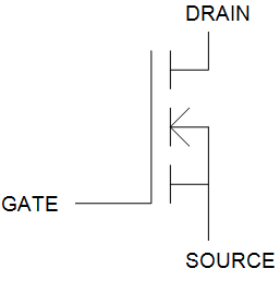
Ich will den rechten oberen Mosfet spiegeln, sodass beide Sources verbunden sind. Kann mir vl jemand helfen.
LG didi_500
Anbei ein Bild, damit nicht die fragen kommen wo Source bei dem Bauteil ist

\documentclass{scrartcl}
\usepackage{circuitikz}
\usepackage{tikz}
\usepackage{float}

\usepackage{tikz}
\usepackage{subcaption}
\usepackage{caption}

\usetikzlibrary{positioning}
\usetikzlibrary{shapes,arrows}
\tikzset{block/.style = {draw, fill=white, rectangle,
                  minimum height=3em, minimum width=2cm},
        input/.style = {coordinate},
        output/.style = {coordinate},
        pinstyle/.style = {pin edge={to-,t,black}}
    }

\begin{document}

\begin{circuitikz}[auto, node distance=2cm,>=latex']
\node[block](tx){Quelle};
\node[block,right = 8cm of tx](rx){Load};

  \draw (5,0)
  node[draw,minimum width=6cm,minimum height=4cm] (load) {}
  ($(load.west)!0.75!(load.north west)$) coordinate (la)
  ($(load.west)!0.75!(load.south west)$) coordinate (lb)
  ($(load.east)!0.75!(load.north east)$) coordinate (lc)
  ($(load.east)!0.75!(load.south east)$) coordinate (ld)
  (lb) to[short,-o] ++(-2,0) coordinate (lb)
  (la) to[short,-o] ++(-2,0) coordinate (la)
  (lc) to[short,-o] ++(2,0) coordinate (lc)
  (ld) to[short,-o] ++(2,0) coordinate (ld);

  \draw
  ($(tx.north)$) coordinate (top)
  ($(tx.south)$) coordinate (bottom)
  (top) to[short,-o] ++(0,0.911) coordinate (top)
  (bottom) to[short,-o] ++(0,-0.911) coordinate (bottom);

  \draw
  ($(rx.north)$) coordinate (topr)
  ($(rx.south)$) coordinate (bottomr)
  (topr) to[short,-o] ++(0,0.911) coordinate (topr)
  (bottomr) to[short,-o] ++(0,-0.911) coordinate (bottomr);

  \draw(4,5) node[nigfete, rotate = 90] (nmos) {};
  %\node[] at (6,5) {$S$};
 \draw (5.5,5) node[nigfete, rotate=90]{};
  %\node[] at (6,5) {$S$};
  \draw (3.23,1.5) to [L] (6.27,1.5);
  \draw (3.23,1.5) --(3.23,5);
  \draw (6.27,1.5) --(6.27,5);

  \draw (3.2,1) to [C,*-*] (3.2,-1);
  \draw (4.7,1) to [D,*-*] (4.7,-1);
  \draw (7,0) node[nigfete] (nmos) {};

  \begin{scope}[shorten >= 10pt,shorten <= 10pt,]

\draw[->] (1.7,1) -- node[left] {$U_1$} (1.7,-1);
\draw[->] (8.3,1) -- node[right] {$U_2$} (8.3,-1);
\draw[->] (0.5,1.5) -- node[above] {$I_1$} (1.5,1.5);
\draw[->] (9,1.5) -- node[above] {$I_2$} (9.5,1.5);

\end{scope}


\end{circuitikz}


\end{document}
- Dateianhänge
-

- Bildschirmfoto 2017-08-05 um 01.45.17.png (11.95 KiB) 2635 mal betrachtet
Hey Leute,
Ich will den rechten oberen Mosfet spiegeln, sodass beide Sources verbunden sind. Kann mir vl jemand helfen.
LG didi_500
Anbei ein Bild, damit nicht die fragen kommen wo Source bei dem Bauteil ist ;)
[code]
\documentclass{scrartcl}
\usepackage{circuitikz}
\usepackage{tikz}
\usepackage{float}
\usepackage{tikz}
\usepackage{subcaption}
\usepackage{caption}
\usetikzlibrary{positioning}
\usetikzlibrary{shapes,arrows}
\tikzset{block/.style = {draw, fill=white, rectangle,
minimum height=3em, minimum width=2cm},
input/.style = {coordinate},
output/.style = {coordinate},
pinstyle/.style = {pin edge={to-,t,black}}
}
\begin{document}
\begin{circuitikz}[auto, node distance=2cm,>=latex']
\node[block](tx){Quelle};
\node[block,right = 8cm of tx](rx){Load};
\draw (5,0)
node[draw,minimum width=6cm,minimum height=4cm] (load) {}
($(load.west)!0.75!(load.north west)$) coordinate (la)
($(load.west)!0.75!(load.south west)$) coordinate (lb)
($(load.east)!0.75!(load.north east)$) coordinate (lc)
($(load.east)!0.75!(load.south east)$) coordinate (ld)
(lb) to[short,-o] ++(-2,0) coordinate (lb)
(la) to[short,-o] ++(-2,0) coordinate (la)
(lc) to[short,-o] ++(2,0) coordinate (lc)
(ld) to[short,-o] ++(2,0) coordinate (ld);
\draw
($(tx.north)$) coordinate (top)
($(tx.south)$) coordinate (bottom)
(top) to[short,-o] ++(0,0.911) coordinate (top)
(bottom) to[short,-o] ++(0,-0.911) coordinate (bottom);
\draw
($(rx.north)$) coordinate (topr)
($(rx.south)$) coordinate (bottomr)
(topr) to[short,-o] ++(0,0.911) coordinate (topr)
(bottomr) to[short,-o] ++(0,-0.911) coordinate (bottomr);
\draw(4,5) node[nigfete, rotate = 90] (nmos) {};
%\node[] at (6,5) {$S$};
\draw (5.5,5) node[nigfete, rotate=90]{};
%\node[] at (6,5) {$S$};
\draw (3.23,1.5) to [L] (6.27,1.5);
\draw (3.23,1.5) --(3.23,5);
\draw (6.27,1.5) --(6.27,5);
\draw (3.2,1) to [C,*-*] (3.2,-1);
\draw (4.7,1) to [D,*-*] (4.7,-1);
\draw (7,0) node[nigfete] (nmos) {};
\begin{scope}[shorten >= 10pt,shorten <= 10pt,]
\draw[->] (1.7,1) -- node[left] {$U_1$} (1.7,-1);
\draw[->] (8.3,1) -- node[right] {$U_2$} (8.3,-1);
\draw[->] (0.5,1.5) -- node[above] {$I_1$} (1.5,1.5);
\draw[->] (9,1.5) -- node[above] {$I_2$} (9.5,1.5);
\end{scope}
\end{circuitikz}
\end{document}[/code]