von Orikson » Do 20. Aug 2015, 00:37
Hat den niemand eine Idee woran das liegen könnte? Bei größeren Zeichnungen wird der Effekt noch willkürlicher

\begin{figure}[H]
\begin{circuitikz}
\draw[color=black, thick]
% modulation source
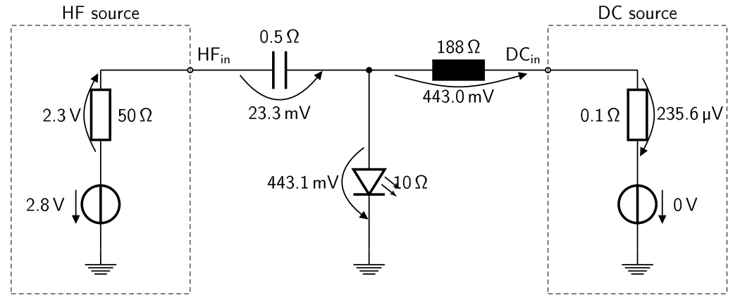
(0,0) node[ground]{} to [V<=$\SI{2.8}{\volt} $] (0,2)
to [R, l_=$\SI{50}{\ohm}$, v^>=$\SI{2.3}{\volt}$] (0,4)
to [solid, -o] (2,4)
% HF C
node[above right]{$HF_{in}$} to [C, l=$\SI{0.5}{\ohm}$, v_>=$\SI{23.3}{\milli\volt}$, o-] (6,4)
% DC L
to [L, l=$\SI{188}{\ohm}$, v_>=$\SI{442.9}{\milli\volt}$, -o] (10,4) node[above left]{$DC_{in}$}
% current source (shortened)
to [solid, o-] (12,4)
to [R, l_=$\SI{0.1}{\ohm}$, v^>=$\SI{235.6}{\micro\volt}$] (12,2)
to [V=$\SI{0}{\volt}$] (12,0) node[ground]{}
% LED
(6,4) to [short, *-] (6,3)
to [leDo, l=$\SI{10}{\ohm}$, v_>=$\SI{443.1}{\milli\volt}$] (6,0) node[ground]{}
;
\draw [densely dashed]
% box around HF source
(-2,-1) to +(4,0)
to +(4,6)
to node [above,pos=0.5] {HF source} +(0,6) %Beschriftung
to +(0,0)
;
\draw [densely dashed]
% box around DC source
(10,-1) to +(4,0)
to +(4,6)
to node [above,pos=0.5] {DC source} +(0,6) %Beschriftung
to +(0,0)
;
\end{circuitikz}
\end{figure}
- Dateianhänge
-
- Unbenannt.PNG (42.81 KiB) 1603 mal betrachtet
Hat den niemand eine Idee woran das liegen könnte? Bei größeren Zeichnungen wird der Effekt noch willkürlicher :shock:
[code]\begin{figure}[H]
\begin{circuitikz}
\draw[color=black, thick]
% modulation source
(0,0) node[ground]{} to [V<=$\SI{2.8}{\volt} $] (0,2)
to [R, l_=$\SI{50}{\ohm}$, v^>=$\SI{2.3}{\volt}$] (0,4)
to [solid, -o] (2,4)
% HF C
node[above right]{$HF_{in}$} to [C, l=$\SI{0.5}{\ohm}$, v_>=$\SI{23.3}{\milli\volt}$, o-] (6,4)
% DC L
to [L, l=$\SI{188}{\ohm}$, v_>=$\SI{442.9}{\milli\volt}$, -o] (10,4) node[above left]{$DC_{in}$}
% current source (shortened)
to [solid, o-] (12,4)
to [R, l_=$\SI{0.1}{\ohm}$, v^>=$\SI{235.6}{\micro\volt}$] (12,2)
to [V=$\SI{0}{\volt}$] (12,0) node[ground]{}
% LED
(6,4) to [short, *-] (6,3)
to [leDo, l=$\SI{10}{\ohm}$, v_>=$\SI{443.1}{\milli\volt}$] (6,0) node[ground]{}
;
\draw [densely dashed]
% box around HF source
(-2,-1) to +(4,0)
to +(4,6)
to node [above,pos=0.5] {HF source} +(0,6) %Beschriftung
to +(0,0)
;
\draw [densely dashed]
% box around DC source
(10,-1) to +(4,0)
to +(4,6)
to node [above,pos=0.5] {DC source} +(0,6) %Beschriftung
to +(0,0)
;
\end{circuitikz}
\end{figure}[/code]